Archive for the ‘Upgrades’ Category

So as I’m going to have the majority of my car apart this winter for the supercharger installation and various maintenance items… which may include an exhaust (fingers crossed), I decided to do some preventative upgrades.

Since there is already a very good DIY (need to be a forum member to see pics), I’ll just post the links to get all the information and where I purchased.

First the 6speed link that started it all:  http://www.6speedonline.com/forums/996-vendor-classifieds/201845-fs-2nd-gear-pop-out-diy-fix-cheap-insurance-2.html
The DIY link for the tranny in car:  http://www.renntrack.com/forums/showthread.php?1278-Detent-DIY
The eBay link for where I purchsed:  http://cgi.ebay.com/ebaymotors/ws/eBayISAPI.dll?ViewItem&item=160486815697#ht_652wt_941

Yay, more tasks to complete…

Cheers
Aaron

Hi all,

I haven’t been up to much in this past year as I’ve been busy with family, work, and house project commitments…

I was also wondering what to do with my car, and I came to the conclusion to sell it and buy a slightly newer Turbo to get some better performance.  This conclusion was quickly dashed when I took a look at the market and Kelly Blue Book was stating $16,500 – $22,500 USD for a C2 of my year.  The Turbo’s I was looking at were $40,000 – $56,000 USD.

So, with that I’ve decided to keep the car and thus continue with the original plans on upgrades.  At the moment, the only two outstanding issues are exhaust and some more HP.  This may seem a little backwards, however, Vivid Racing did a special on their VF Supercharger kit that I’ve had my eyes on for some time now so I guess I’ll be getting my HP upgrade before my exhaust upgrade!  🙂

Thus, this is the first post of what I trust will be many as this is NOT an easy installation!!!

Cheers
Aaron

Hi all,

I found this information after much searching for GT3 ride height settings.  In looking at them, I’m going to go with ROW Sport to start as the car needs to be streetable and I’d like to save some of the life on the rear tires… it will be a starting point anyways.

As taken from:  http://www.lfsforum.net/showthread.php?t=4060
—————–

RoW Sport:
Front ride height: 138mm
Rear ride height: 148mm
(I don’t know how to convert the spring rates (front 170lbs/in rear 260lbs/in)to kN/m…
…so I guessed them)
Front spring rate: 60kN/m
Rear spring rate: 75kN/m
I don’t know the anti-rollbar stiffness but I know the ratio between front and rear – 0.436. (I calculated from it from the table 2) So, if the front stiffness is lets say 35kN/m the rear stiffness is 15.3kN/m.
You can calculate the damper values from the chart 9 and 10. I can’t…
Steering lock:
(911 GT2: ratio: 16.9:1, turns, lock-to-lock: 2.98)
So it’s nearly 32 degrees which is quite low actually…
LSD:
(Again from 911 GT2)
40% power, 60% coast
Camber:
Front -0.5 degrees
Rear -1.25 degrees
Toe-in:
Front ~0.1 degrees
Rear ~0.2 degrees
Tire pressure (for Boxter 17″ wheels):
Front 29psi ->2 bars
Rear 36psi->2.5bars
GT3:
Front ride height: 112mm
Rear ride height: 125mm
I don’t know the spring rates so I guessed:
Front 75kN/m
Rear 90kN/m
Both of them are very stiff but GT3 has very harsh ride I think..
Camber:
Front -1 degrees
Rear: -1.83 degrees
Tire pressure:
Front 32psi->2.2bars
Rear 39psi->2.7bars
Sources:

RoW Sport:

Front ride height: 138mm
Rear ride height: 148mm
(I don’t know how to convert the spring rates (front 170lbs/in rear 260lbs/in)to kN/m…
…so I guessed them)
Front spring rate: 60kN/m
Rear spring rate: 75kN/m
I don’t know the anti-rollbar stiffness but I know the ratio between front and rear – 0.436. (I calculated from it from the table 2) So, if the front stiffness is lets say 35kN/m the rear stiffness is 15.3kN/m.
You can calculate the damper values from the chart 9 and 10. I can’t…
Steering lock:
(911 GT2: ratio: 16.9:1, turns, lock-to-lock: 2.98)
So it’s nearly 32 degrees which is quite low actually…
LSD:
(Again from 911 GT2)
40% power, 60% coast
Camber:
Front -0.5 degrees
Rear -1.25 degrees
Toe-in:
Front ~0.1 degrees
Rear ~0.2 degrees
Tire pressure (for Boxter 17″ wheels):
Front 29psi ->2 bars
Rear 36psi->2.5bars

GT3:


Front ride height: 112mm
Rear ride height: 125mm
I don’t know the spring rates so I guessed:
Front 75kN/m
Rear 90kN/m
Both of them are very stiff but GT3 has very harsh ride I think..
Camber:
Front -1 degrees
Rear: -1.83 degrees
Tire pressure:
Front 32psi->2.2bars
Rear 39psi->2.7bars

Sources:


Hi all,

So I finished the rear today and I can confirm that Turbo rotors and calipers are a direct bolt on.

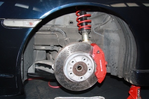
I also installed the H&R coil overs, rear adjustable control arms, and GT3 toe links.  I then installed the GT2 adjustable sway bar with new bushings and the Agency Power sway bar links.  I put the settings to factory GT3 settings as I did with the fronts.  I’m also using 7mm H&R spacers on the rear for now and I have 15mm that I’ll be trying on the fronts.  These may all change though and I’ll update if I do.

I’m going to need to play with the ride height settings to get them probably to GT3 RS settings, but the majority of the fine tuning will be done during the alignment.  Here are a few pictures of the results:

IMG_5815

IMG_5817

IMG_5819

IMG_5822

IMG_5828

IMG_5826

IMG_5833

Cheers
Aaron

Hi all,

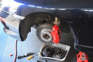
Well after sourcing much of the little bits that frustrated you, I can report that I have successfully installed 996 TT brakes on my C2.  I also hung the new 997 C2S “Lobster Fork” wheels on to see how it all looks together… and I can say, I like it!

Now I have to button up the other side and move to the rear, which should be a little easier as everything is bolt on.  However, those have been known to be famous last words…

Here are a few pictures:

IMG_5788

IMG_5790

IMG_5792

Cheers
Aaron

Hi all,

So this past weekend I started on my project, and let me make it clear that I am in no rush here as there is no documented DIY on this so I need to make sure everything is done 100% correct.  This means much research and talking to as many people as I can on the subject.  Finding someone that has done this themselves before, or works for a custom shop and has done this, is very rare.

Okay, so obviously I am going to start with the front as the wheel carriers are the big unknown in this project.  I’ve found a few people that have had this done and they 996 TT wheel carriers were installed, so its possible.

Few things I’ve ran into so far:

  1. The strut mount on the 996TT I.D. is 2.165″ and on the C2 it is 2.040.  A difference of 0.125″ or 1/8″ – This will require a sleeve to be made from brass in 1/16″ or 16ga.  I’ve seen other coil over companies sell sleeves for their TT versions, so its a valid solution.
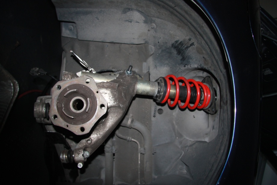
  2. Due to TT being AWD, the mount is also very off-center from the upper body mount and the lower control arm pivot.  See picture below. – This will require that I install the camber plates from stock 996 TT

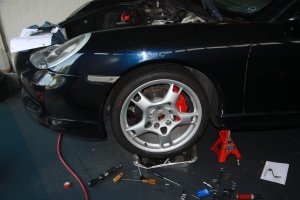
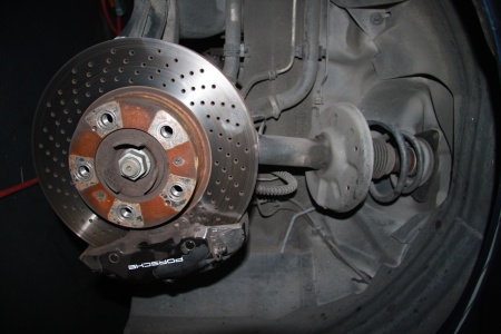
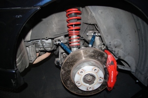
Everything else bolts up just fine so far in my test fitting.  I’m only going to do one side until I figure it out 100% before doing the other so I have a reference point.  I’ve included a couple pictures here as you can then see how dramatic a difference there will be in your strut positioning.

Also, when the wheel carrier now turns, you will see the lower part of the strut move in and out due to the off set of the strut mount in the TT wheel carrier.  It makes total sense look at it, but in seeing only C2’s it seems very odd as it doesn’t do that on the other side.  I’m verifying this behaviour by looking at a local club member’s TT and also with a few Porsche mecahnics just to make sure.

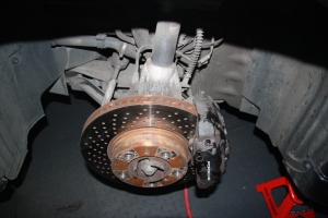
Passenger Side – During Test Fitting

IMG_5783

IMG_5784

Driver’s Side – Still Stock Configuration

IMG_5785

IMG_5786

Cheers
Aaron

Hi all,

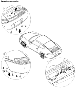
Here we are at Part 2 and it looks like to get this done right its time to remove the rear bumper…

As per Porsche, here is the instructions:

rearbump

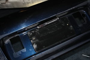
So with the bumper off this is quite easy.  Just drill a hole and insert the wiring/supplied grommet.  The one thing is that you will end up drilling the hole behind the Porsche license plate holder.  You will need to notch out the holder slightly on the top so you don’t pinch the wiring when you put everything together.

This is also a great time to seriously clean the bumper while its off as there is a lot of grime you’ll find behind the bumperettes.

img_3752

So now you have the diffuser installed, you will see something that looks like this:

img_3753

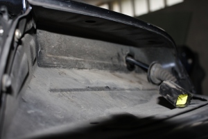
I ran my wire through the right side hole, for reasons you are yet to see… this hole leads right behind the trunk latch and is easily fed through.  Feed the wiring through but don’t forget to leave a few feet of extra wire on the BUMPER side or outside of the body.  This way if you ever need to remove the bumper again you have some slack to do so.  You want this on the bumper side as extra wiring hanging around in the engine bay is a BAD idea.

Once you are done feeding the wires through you can reinstall the bumper.

Now comes the fun part.  If you remove the Passenger side tail light and then remove the grommet and wiring through the back of the housing.  When you look through the hole you have just liberated, you will see a very large grommet that leads into the body.

img_3747

img_3748

Ok so you will use a drill with a long bit through the hole from the Passenger rear tail light compartment to the very top side FAR AWAY from the existing wires.  Go slow, take your time, as you don’t want to drill wiring.

My bit wasn’t long enough to go all the way through, but about 7/8ths the way.  So I used a flat head to poke the rest of it… probably a good approach anyways as its not a good idea drilling into a cavity blind unless you’re sure what’s on the other side.

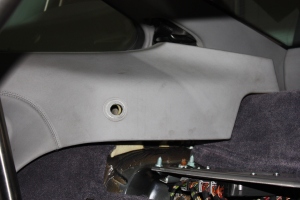
So now you will need to remove the Passenger side interior panel:

img_3750

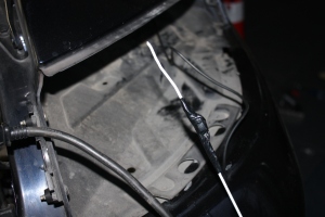
Now for the old coat hanger trick… run the diffuser wiring through the back side of the tail light housing through that hole where the grommet was and use electrical tape to fasten it to the coat hanger.  I also recommend using a bit of grease on the taped area as you don’t want this getting all jammed up and not being able to get it through or out…

img_3754

Punch this through as far as you can and reach inside the Passenger side fender area and you can pull the whole thing through.  Zap strap the loose wires in the engine bay, reinstall the wiring and grommet into the tail light housing, reinstall the tail light and you can close up the engine lid as we’re done here…

I ran the wiring down the Passenger side of the car down to the lower carpet seam where the front lower seat belt bolts to the body.  Then I ran it down the line to the console… time to remove the console!

img_3745

You can use the Schnell, B&M, or any other directions you want to remove the console.  The Schnell one is as good as any and can be found here: http://www.vertexauto.com/showitem.aspx?id=197844&name=Porsche%20996%2C%20997%20%26%20Boxster%20Short%20Shift%20Kit%20Schnell&

The main control unit I installed behind the area where the stereo was and the “display” I mounted in the rear comparment of the console.  This is so its hidden but I can access it if I want to turn it off.  I’ll probably also make a cover for it so its more hidden.

I tested it all and I got green lights so looking good.  If you decide to also test this with your seats out, you will get an Air Bag light code.  I have the Durametric software so I didn’t care as I just cleared the codes after the fact.

As to the remote mute, I have sourced a couple window switches and replace one of the dead switches in the ashtray area.  It is very easy to get at so I’ll be doing this in the future as this project was holding me back from other things and getting my car on the road.

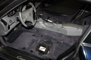
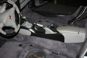
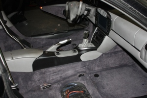
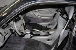
I also preped and painted my center consol to match more of the grey/black theme with the factory carbon fiber as well as the grey/black in my newly installed GT3 seats.

Here is a couple after shots with all the work done..

img_3755img_3756

img_3757

I know, one set of GT3 seat inserts is Alacantra and the other is leather… That is since one seat was originally black and I changed the color (can be seen on another post).  The other seat was originally grey but the previous owner had a black interior so changed the center pads to match… ironic.

Anyways, will be putting the Alacantra back to leather when I can source an existing insert or have it recovered.

Cheers
Aaron

Hi all,

Well this weekend I decided to tackle the Escort ZR3 Laser Diffuser/Shifter Installation.

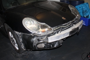
To install it correctly, it is required that you remove the front bumper to properly route the wires, etc.  While you’re in there, clean your radiators! This includes unbolting and moving the condensers out of the way to get behind there.. its really ugly how much stuff gets in there so do it.

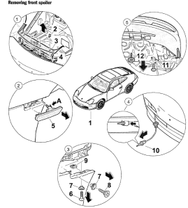
Here are the instructions on how to removed the bumper.  If you are a religious man and don’t like to swear, have a friend do the 3-6 screw… you have been warned.

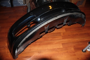
bumper1So you have your bumper off and you have removed the ducts and cleaned all the radiators.  I also took the time to clean the bumper all nice as it just makes life easier when working with it.  Here are some pictures.

img_3727

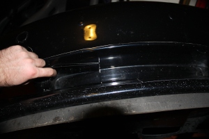
Obviously you can tell my car is a factor Aero Kit car, so this is an Aero bumper.  This is where things may get a little different for your installation but things should be quite similar.

img_3730

First thing you need to do is plan the installation of the brackets.  You don’t want to drill your nice Porsche bumper to Swiss cheese, so make sure you have it right.  Remember, these things need to be flat and level with the road ahead, not follow the nice curve of your bumper.

I did have an option of cutting out the center area as if I was installing the GT3 front radiator to get them sunken in behind the bumper out of site, however I didn’t want to drill into the sheet metal and I also didn’t want to mess with the aerodynamic properties of the bumper as I feel opening this up would reduce overall downforce.  A nice feature to have at high speeds in an ass heavy Porsche…

img_3732

So I marked the holes to mount the bracket and I drilled the hole for the wiring.  There is a rubber grommet included on the wiring so this get all finished off nice when its in place.

img_3733

There is the first one done all mounted and the grommet in place.  Due to the curve of the bumper, this will stick out on one side of the diffuser from the bumper making it a visible item.  I’m not too happy about that as I like things all flush and factory, however given the option of ruining aerodynamics I can live with it.  Also my car is Ocean Blue Metallic aka really dark, so they don’t show up much after its on the car.

img_3734

His friend installed as well… I’ve heard that the further the separation of these the better, however there is no room in the air inlet area of my bumper.  Plus then I’d be putting something in the way of the air intake for the cooling system and again, I didn’t like that option.

img_3735

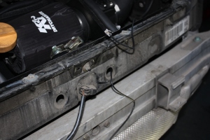
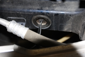
Ok bumper is ready, now the meat of it… In the front structural area of the car you will see two grommets.  One is used for wiring and the other is used for nothing.  Packed full of convience…  Just make a few small cuts and run the wires…

img_3737

… like this.

img_3738

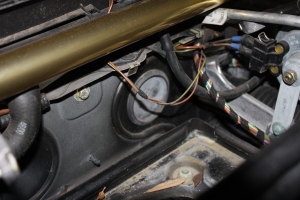
So I ran the wires up the Driver’s side of the inside trunk area and behind the brake plumbing.  I then noticed that there was another unused grommet behind the CD stacker on the passenger side… so I ran the wiring behind the brake booster, amplified, and CD stacker through this second unused grommet…

img_3740

… like this.

img_3741

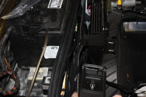
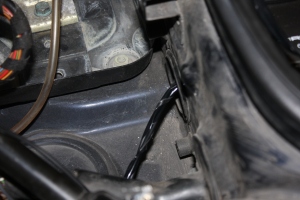
So to get it into the car.  You need to remove the battery to accomplish this and while you do, take the time to clean your terminals and battery posts as this should be a regular thing anyways.  On the Driver’s side you will find… guess it… another third unused grommet!!!  Few cuts and run the wires…

img_3742

… like this.   There is nothing behind there and you just push them right through.  Reach up behind the pedals and pull them through.  For now I have tucked the wires up and out of the way as I will be doing the final portion of the installation next weekend.

img_3743

Time to reinstall the bumper and put the front boot area all back together again…

bumper2

That’s that for Part 1.  In Part 2 I will be showing the installation and wiring of the rear component specifically and in the final Part 3 I will show where I decided to put the final parts of the components including a nifty solution to where to install the remote mute button.

Cheers
Aaron

Hi all,

Well as I mentioned I decided to replace the wheel bearings before I go about replacing the wheel carriers on my C2 with the Turbo ones.  However, the PIA thing about doing the job is getting it done 100% correctly and that involves special tools and heating them just right.

Although I’m not scared of doing the job, I do lack a torch and some of the puller tools handy so I’m going to pass this one off to a local independent shop I use called Scan Automotive.  They’ve done great work on my car in the past for things I couldn’t handle so I’m sure they will get these just right as well.

For anyone that is looking to do this, there was a DIY posted on Renntech that I’ll put up here for the sake of having all the information in one place.  This is a bit of a risky DIY, so please take it as information purposes only.

Cheers
Aaron

————–

Now let me say that this job was quite straightfoward, BUT I would suggest that you have a bit of experience in bearing fittting as well as presswork or you may really mess things up in a big way. You also need a ball joint service puller set, and yes you need ALL the tools in the kit.

I got mine from OTC/ msc industrial supply cat #78453842. You will also need a way to make some mandrels for pressing the bearings in and out. And a way to heat the carrier to around 150 degrees.

Now for the fun

1) jack up car and place on jackstands, remove front wheels
2) remove front plastic underpanel
3) have someone hold the brakes (hard) and remove the front large (1.25″) axel nut, this is TIGHT 340 ft.lbs. so get ready for a fight.

4) with a brass or aluminium mandrel and a hammer tap, (ok smack), the drive shaft to dislodge it from the splines of the hub (don’t mess up the threads!!!)
5)Remove the brake pads and the brake caliper (hex drive) tie it up in the wheel well out of the way
6)Remove the psm sensor, move it to the side (2 10mm nuts)


7)unbolt lower sway bar link
8)unbolt headlight sensor link
9)Remove the brake rotor
10) Remove tin brake shield (10mm bolts)
11) remove 18mm nut and press apart tie rod link with the tool

12) remove the 18mm nut and carefully use the tool to press apart the lower ball joint

13) Unbolt the clamp on the strut, then while pressing down on the lower arm slide the carrier off the strut and the front axel (gt2 remove axel-bearing retainer) and take to the bench

14) Now from the rear side carefully press the center hub out of the bearing, It will come apart with 1/2 the bearing attached to the center hub, it is TIGHT
and will take a bit of force to remove it. Be careful NOT to hurt the carrier as it is $$$ if you break it

15) With a puller remove the center race(the part that was left on the shaft) from the hub, set aside

16) take off the 4- 13mm bolts and remove the bearing retainer plate from the carrier
17) HEAT (and DO NOT skip this step) the carrier to 100 deg,F and with a mandrel press/drive out the bearing from the carrier, again BE CAREFUL when suporting the carrier!!!!
18) Clean all parts.

19) Now the bearing is about a .0035 PRESS fit in the carrier, you CANNOT just press it in cold, you MUST heat the carrier to get it in, there are 2 methods to do this

  • heat carrier to 100 deg F and using a mandrell that touches only the outer part of the bearing press in the new bearing
  • set a inside micrometer to .004 over the bearing size, then heat the carrier to around 150 deg F, at this point check size with the mike to make SURE the carrier is over the size of the bearing and drop the bearing into the carrier, it will slip right in with no force at all, HOWEVER if you goof up and it sticks 1/2 way you are screwed.

20) Replace the bearing retainer plate with the 4 bolts, if yours has it the small notch goes to the bottom, its a water drain, torque the bolts, 27 ft lbs
21) Very carefully suporting the inner bearing race only,press in the wheel hub to the stop, be careful not to hurt your new bearing. WATCH what you press on!!!!!
22) assemble in reverse order, center 1.25 nut torques to 340 ft,lbs.
23) make sure to torque all bolts/nut to the correct values and double check all bolts.nuts before driving

As you can see this bearing was SHOT, 26,000 miles and sounded like road noise, it did not respond to any tests like a bad bearing at all, so check your bearings!!! Thanks to Jeremy at Imagine Auto for the quick service and the tips, you guys are great !!

Good luck !! Do this repair at your own risk, this diy is just provided as a general guide.
Hi all,

This is one of the most controversial upgrades out there as many people will go straight to a GT3 upgrade and many others don’t know how to do this.  So, to find a complete DIY has in my experience been historically impossible.
So, why go with a Turbo upgrade?  Well the larger rotors and calipers allow for about 35% more pad surface to rotor versus the C2 and also allows for rapid heat displacement in harder applications such as track usage.  Yes, they are also red and have a “cool” factor that comes along with doing the upgrade… however if that is all you want out of this I’d just powder coat your original ones!
GT3 versus Turbo… Well the issue here is that you will not be able to use GT3 front rotors due to the offset being all wrong for a C2.  You can however use Turbo rotors.  The GT3 calipers are six piston versus the Turbo four piston so there is a more dramatic braking performance gain.  There is also a massive increase in the budget and since there are a few totalled Turbos out there and people that upgrade to six piston GT3 or Brembo kits, a set of stock Turbo calipers can be found much easier for much less.  So, I went Turbo…

Now the following information on what you need would not be possible without Steve Weiner’s help from Rennsport Systems.

You will need to replace the following items on your C2 if you wish to do this:

  • Front wheel carriers and hubs (rears stay unchanged)
  • Master cylinder with one from a C4S or Turbo (same part number) to handle increased volumetric requirements – My C2 has PSM and both C4S and Turbo has it as well
  • 996 Turbo front and rear calipers
  • 996 Turbo front and rear rotors
  • 996 Turbo front and rear brake lines

After about a month of searching I was able to source the parts with costs as follows (in USD):

  • Full 996 TT brakes with rotors, pads, calipers, and lines: $600 – Used, 6speedonline.com
  • Front L/R Wheel Carriers and Hubs complete: $800 – Used, LA Dismantlers
  • Master Cylinder from C4S/Turbo: $323 (went with a new one, used is $250) – Suncoast Porsche
  • Front bearings (optional, but while they are off…): $62.84 each (x2) – Suncoast Porsche

Total cost, with the optional of:  $1,848.68 USD

Cheers
Aaron

———–

REFERENCE INFORMATION

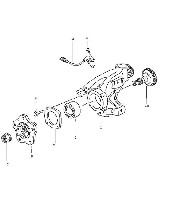
Just in case you don’t know what a wheel carrier is/looks like, here is an exploded diagram of what one looks like from a 996 Turbo:

ttwc1